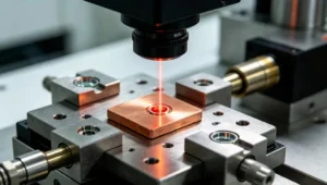
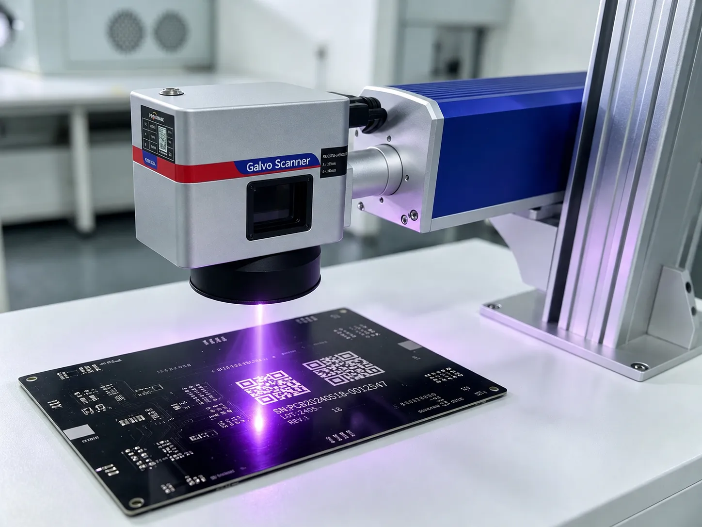
Cold, sub‑micron precision marks are now part of many production acceptance criteria. 355nm UV lasers deliver those marks while keeping part integrity intact.
355nm UV lasers reduce thermal damage, enable ultra‑fine features, and mark transparent or heat‑sensitive materials with minimal residue.
The following covers technical rationale, six practical advantages, industry examples and pain points, a procurement comparison with fiber and CO2 lasers, selection specs (including thermal control), and vendor configuration guidance.
1. Introduction: The Evolution of Precision Marking in Modern Manufacturing
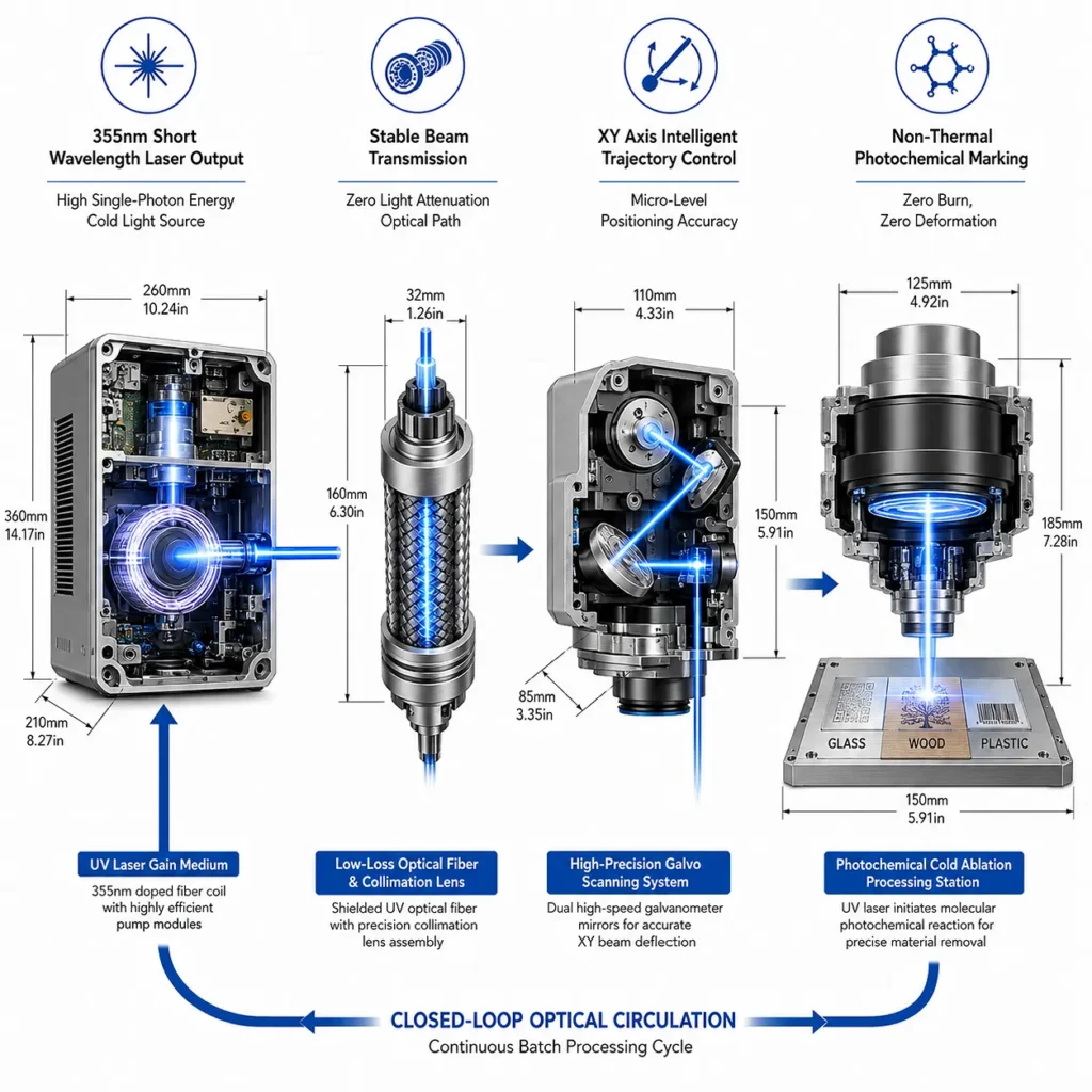
Manufacturing moved from mechanical stamps to thermal lasers because speed and durability matter. Thermal processes often damage micro‑features. Short‑wavelength UV introduced more photochemical pathways. At 355 nm, single photon energy (~3.49 eV) approaches or exceeds many organic bond energies (for reference: C–C ≈ 3.6 eV, C–N ≈ 3.1 eV). That enables direct bond breaking rather than bulk heating. The result is much lower collateral heat and finer control over material removal or modification.
Photochemical effects dominate at 355 nm. Thermal effects still occur with longer pulses or higher average power. Industrial 355 nm systems are typically nanosecond class; true ultra‑cold processing requires picosecond–femtosecond regimes and tighter control over beam quality and pulse energy.
2. 6 Key Advantages of 355nm UV Laser Marking Machines
Minimal heat spread, very small spot sizes, strong contrast on many non‑metal substrates, much less recast, predictable micro‑depth control, and the ability to mark transparent materials are the primary practical benefits.
Advantage 1 — Minimal Heat Affected Zone (HAZ)
At 355 nm, photon energy enables bond scission with lower thermal diffusion. The microstructure around the mark stays intact in most polymers and thin films. For components where temper or heat treatment matters, that reduces scrap and post‑process rework.
Advantage 2 — Ultra‑High Precision and Fine Feature Resolution
Shorter wavelength reduces the diffraction limit. Achievable spot sizes depend on beam quality and optics. For consistent <10 µm spots, target beam quality M2 < 1.2 and use high‑NA optics. Note the pulse regime: industrial 355 nm units are often nanosecond (10–15 ns). Picosecond or femtosecond UV systems reduce residual thermal load further and improve edge definition, but increase cost and system complexity.
Advantage 3 — Superior Contrast on Polymers, Ceramics, and Glass
UV photons can create color centers, surface chemistry changes, or controlled micro‑roughness. That yields higher contrast on PC, ABS, polyimide, glass, and many ceramics without charring typical of IR or CO2 processes. Contrast validation with vision/read systems is important for acceptance.
Advantage 4 — Low Debris, Minimal Recast, and Cleaner Marks
Photochemical ablation produces smaller ejecta and less molten recast than IR ablation. That reduces contamination risk in assembly and lowers filtration loads for fume extraction systems. Cleanliness is critical in medical and optics assembly lines.
Advantage 5 — Fine Depth Control for Micro‑Machining
Depth control comes from pulse energy, pulse count, and repetition rate. Use cross‑section metrology to correlate energy per pulse to depth per pass. Picosecond regimes offer the finest depth control with minimal thermal accumulation.
Advantage 6 — Effective Marking on Transparent and Thin Films
Subsurface modification, color center formation, or micro‑roughening lets UV mark glass, lenses, and thin films while preserving optical transmission elsewhere. Validate residual stress and transmission post‑process for optical components.
3. High-Value Industry & Creative Applications
355nm UV lasers are already solving real shop‑floor pain points. Examples below link capability to concrete outcomes and acceptance metrics.
PCB / Microelectronics
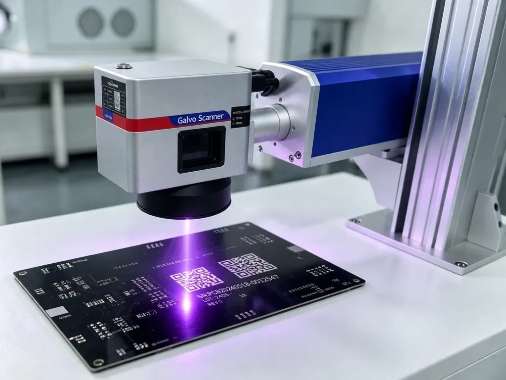
Problem: IR fiber lasers can carbonize solder masks or eject conductive debris that risks shorts.
Outcome with 355 nm: High‑contrast marks on FR4 or chip packaging without damaging dielectric layers. Validation: electrical continuity testing, solderability tests, visual inspection post‑reflow.
Medical Devices
Problem: Heat or surface damage can invalidate passivation or biocompatibility.
Outcome with 355 nm: IDs on catheters, tips, and implants with minimal effect on surface chemistry. Validation: cytotoxicity tests, corrosion resistance, and durability under sterilization cycles.
Optics & Lenses
Problem: Thermal marking warps lenses or creates zones of altered refractive index.
Outcome with 355 nm: Frosted or subsurface marks with acceptable wavefront error. Validation: interferometry, transmission and scattering metrics.
Luxury Goods & Personalized Jewelry
Problem: Visible marks must be ultra‑fine without compromising finish.
Outcome with 355 nm: Crisp logos and serials that meet aesthetic tolerance. Validation: colorimetry, visual QA and abrasion testing.
Acrylic Crafts & Signage
Problem: Melting at cut edges degrades finish.
Outcome with 355 nm: Clean edges and fine detail on acrylic without melting. Validation: edge quality ISO tests and color stability.
Include pilot runs that mirror production stressors and lock pass/fail criteria before scaling.
4. Fiber vs. CO2 vs. 355nm UV Laser: Quick Selection Matrix for Procurement
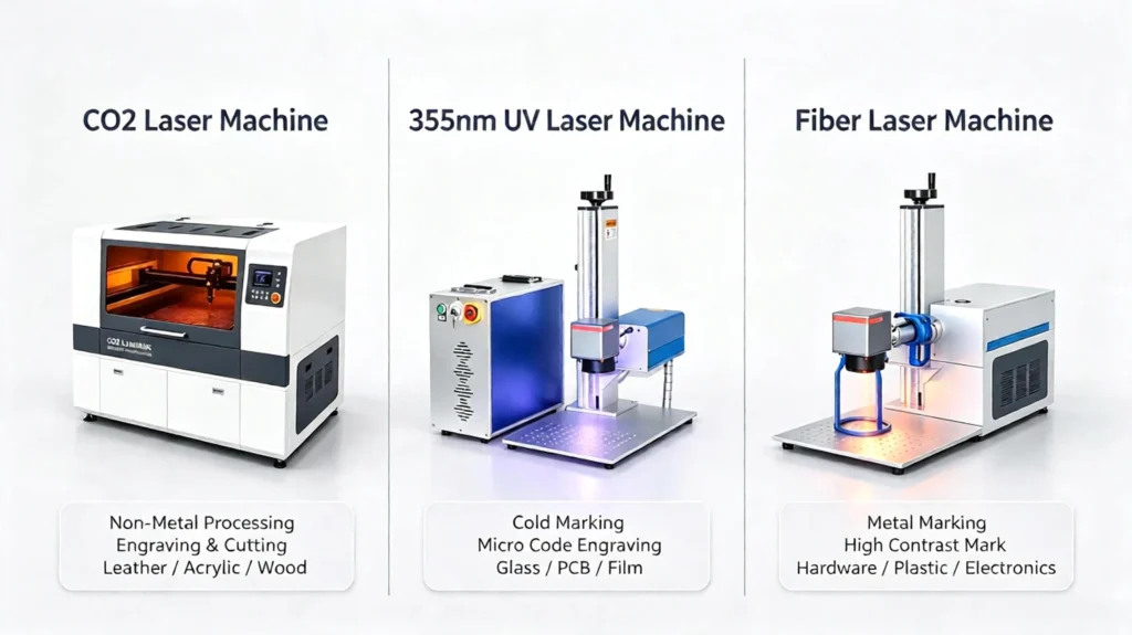
Procurement needs a one‑glance comparison that highlights heat effects, micro‑crack risk, and typical throughput.
| Criterion | Fiber (1064 nm) | CO2 (10.6 µm) | 355nm UV |
|---|---|---|---|
| Best substrates | Metals, some plastics | Wood, fabrics, many plastics | Polymers, glass, ceramics, thin films |
| Heat Affected Zone (HAZ) | Medium | High | Negligible–Low |
| Risk of micro‑cracking | Low on metals; higher on brittle non‑metals | High on some substrates | Negligible if parameters controlled |
| Feature size | Fine (10–50 µm) | Coarser (>50 µm) | Ultra‑fine (<10 µm achievable) |
| Debris / recast | Moderate | High | Low |
| Throughput | High for metal DPM | High for cutting/engraving organics | Moderate; optimized for precision |
| Typical pulse regimes | ns to pulsed fiber | CW or long‑pulse | ns common; ps/fs for ultra‑cold |
| Cooling needs | Air or water for high power | Air or water for high power | Sensitive to temperature; precise water chillers recommended |
| Typical cost | Mid | Low–mid | Higher upfront |
Use this matrix to prioritize risk factors (HAZ, debris, micro‑crack) that affect downstream assembly, compliance, and scrap.
5. Decision-Making Guide: Choosing the Right UV Laser Configuration for Procurement
Selecting the right UV laser system requires balancing beam physics, thermal stability, and total cost of ownership. Use this decision framework to establish strict pass/fail criteria and lock in the right machine setup for your production line.
Step 1: Substrate Sensitivity Threshold Assessment
Determine if 355nm UV is economically justified over Fiber or CO2 based on your material’s thermal tolerance:
- Standard Metals & Rigid Plastics: Opt for Fiber lasers (1064 nm) to keep CAPEX and OPEX low.
- Organic Materials (Wood, Leather, Paper): Opt for CO2 lasers (10.6 µm).
- Heat-Sensitive Polymers, Clear Glass, PCBs, & Thin Films: Proceed with 355nm UV Laser. If surface micro-cracking, charring, or thermal warping is unacceptable, UV cold processing is required.
Step 2: Key Optical & Laser Source Specifications
Demand written guarantees from vendors for these critical technical parameters prior to issuing a purchase order:
1. Beam Quality (M² < 1.2)
- Mandatory Target: M² < 1.2 for sub-10 µm spot sizes and consistent focal depth.
- Risk: M² > 1.3 causes energy dispersion, leading to blurred mark edges and inconsistent processing depth.
2. Pulse Duration
- 10–15 ns (Nanosecond): The industry standard for ~85% of marking applications (PC, ABS, FR4 PCBs, standard glass, thin foils). Balances throughput and cost.
- Picosecond / Femtosecond: Mandatory only when zero HAZ is strictly required (e.g., medical implants, ultra-thin silicon wafers, precision optics). Equipment cost increases by 2.5x to 4x.
3. Power Output Selection
- 3W – 5W: Optimal for static vector marking, micro QR codes, fine glass etching, and low-to-medium line speeds (< 5000 mm/s).
- 10W – 15W+: Required for high-speed Mark-on-the-Fly (MOTF) automated packaging, deep micro-machining, or high-contrast marking on flame-retardant polymers.
Step 3: Thermal Control System Selection (Air-Cooled vs. Water-Cooled)
Third-Harmonic Generation (THG) crystals inside 355nm UV lasers are highly sensitive to thermal fluctuations. Depending on your working environment and duty cycle, both cooling technologies are viable:
Option A: High-Precision Air-Cooling (TEC Integrated)
- Best For: Compact benchtop units, standalone stations, mobile workshops, and environments with normal ambient temperatures (< 30°C).
- Key Advantages:
- Zero Water Maintenance: Eliminates water refilling, deionization filter changes, and leakage risks.
- Compact Footprint: Reduces total machine volume and weight, significantly lowering shipping and integration costs.
- Plug-and-Play: Ideal for high-mix low-volume runs and flexible workshop layouts.
Option B: Dual-Frequency Industrial Water Chiller (±0.1°C Stability)
- Best For: High-temperature factory floors (> 30°C–35°C), 24/7 continuous high-speed production lines, and high-power UV applications (≥ 10W).
- Key Advantages:
- Extreme Thermal Stability: Maintains strict ±0.1°C temperature precision regardless of fluctuating ambient shop-floor temperatures.
- Long-Term Continuous Duty: Prevents power decay and mode-hopping during multi-shift non-stop marking.
- Procurement Recommendation: Choose TEC Air-Cooling for maximum portability, lower footprint, and minimal maintenance; select Water-Cooling if integrating into harsh 24/7 high-temperature automation lines.
Step 4: Machine Form-Factor Selection Matrix
| Form Factor | Primary Target Application | Key Procurement Indicators | Typical Fit / Deployment |
|---|---|---|---|
| Mini Enclosed (Class 1) | Cleanrooms, medical device assembly, standalone stations | High operator safety requirements, optical reflection control, strict dust/fume containment. | High compliance; best for high-mix, low-volume medical or electronics lines. |
| Split / Modular Type | Automated production lines, flying marking (MOTF) | Requires encoder integration, PLC/MES triggers, compact galvo head footprint for line retrofitting. | Lowest footprint; highest throughput for inline conveyor assembly. |
| Desktop / All-in-One | R&D labs, prototype shops, bespoke engraving | Limited floor space, budget constraints, lower daily duty cycle (< 8 hours/day). | Lowest initial CAPEX; ideal for testing, pilot runs, and light production. |
Step 5: Vendor Proof-of-Value (PoV) Acceptance Checklist
Before completing final acceptance, enforce a strict Pass/Fail checklist using your actual production samples:
- Readability Yield: Achieves ≥ 99.5% first-pass barcode/DataMatrix decode rate using automated vision systems (e.g., Cognex, Keyence).
- Material Integrity: Pass dielectric breakdown testing on PCB solder masks; pass salt-spray and autoclave sterilization tests for medical components.
- Laser Stability & Warranty: Require a 24-hour power stability test report (≤ ±3% fluctuation) and locked warranty terms for the THG crystal module (≥ 10,000 operating hours).
6. Conclusion
Deploy 355nm UV when minimal HAZ, micro‑feature fidelity, or transparent/heat‑sensitive substrates are priority. Run real part trials with tight thermal control and beam‑quality specs.
Send representative parts and process targets for a trial. Get a tailored configuration, chiller spec, and validation plan for ROI and production acceptance.Click here to contact ONSLASER Technicians to get premium UV laser marking machines.