Choosing the wrong laser marking machine increases scrap, causes unplanned downtime, and undermines traceability. The decision must follow a clear process‑viability chain: substrate characterization, laser‑source matching, throughput engineering, software‑driven control, and a five‑year TCO assessment.
Early validation on representative production coupons prevents costly rework. Parameter transfer and documented acceptance criteria are required before any serial release.
The sections below present a practical engineering workflow for qualifying machines and locking process parameters for production.
Identify Your Substrate Materials
Establishing a structured validation protocol is critical. Start by cataloguing all substrate families, surface finishes, coating systems and geometric constraints across the product mix. This inventory frames the rest of the decisions.
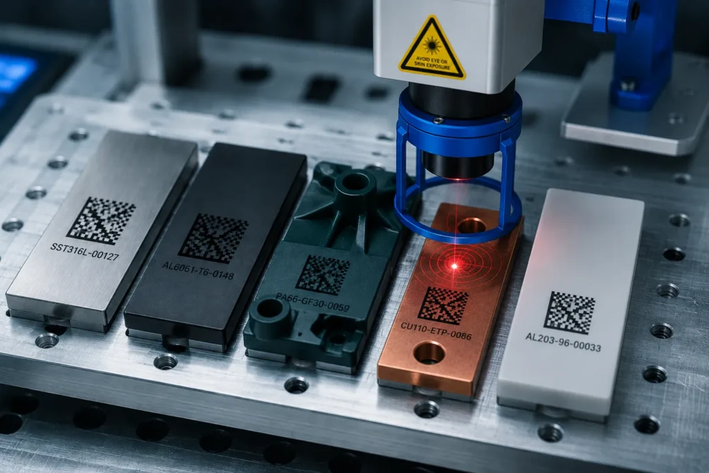
Material absorption behavior and thermal limits determine which laser families are viable. Representative coupons must be processed under production‑like fixturing and handling. Results from those runs become pass/fail criteria in the specifications.
Substrate analysis and test strategy
A practical test matrix covers spectral absorption, visible contrast, tactile depth, and durability under downstream processes. For each substrate class, define measurable acceptance criteria and required tests.
| Test item | Why it matters | Acceptance criterion |
|---|---|---|
| Material family (metal / polymer / ceramic / composite) | Drives laser selection and expected mechanisms | Trial confirms expected absorption and mark quality |
| Surface finish (anodized, painted, PVD, plated) | Changes energy coupling and risk of delamination | Target contrast achieved without coating failure |
| Thermal sensitivity and heat sink effects | Determines pulse regime and repetition strategy | No warpage, discoloration, or microcracks after marking |
| Coating thickness / multilayer stacks | Affects whether annealing, ablation or foaming is used | Clean reveal or stable surface chemistry per spec |
| Geometry, curvature, thickness | Impacts focus control and clamping design | Reproducible focus within defined tolerance band |
Required validation runs include ISO/IEC barcode decode, Taber or equivalent abrasion tests, and any downstream process trials (e.g., plating, tumbling, sterilization). For EV battery and busbar assemblies, include high‑reflectivity copper/aluminum coupons and measure heat‑affected zones and recast layers.
Determine the Right Laser Source
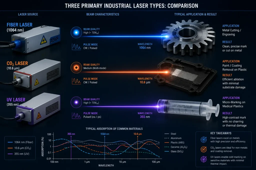
Laser family selection must be driven by physics and downstream durability. Fiber, CO2 and UV lasers interact with materials via different absorption windows and produce distinct thermal footprints. Pulse duration class (ns/ps/fs) further changes surface chemistry and collateral damage.
Fiber (1064 nm) remains the default for steels, stainless and many engineering plastics. CO2 (10.6 µm) is optimal for organics and many paints. UV (355 nm) is used where minimal thermal entry and micron‑scale resolution are mandatory. Ultrashort‑pulse (ps/fs) systems are viable for precision micro‑features and when heat‑free interaction is required, although cost and cycle time must be justified.
Laser source comparison and selection criteria
Selection must reference measured absorption and defined mark durability. For advanced applications—EV connector marking, plated busbars, semiconductor package ID—specific failure modes (recast, redeposition, microcracking) must be part of the acceptance plan.
| Laser source | Engineering strengths | Typical industrial use cases | Key selection checks |
|---|---|---|---|
| Fiber (1064 nm) | High wall‑plug efficiency, robust, compact | Metal part UDI, surgical instruments, housings | Check peak power vs. roughening; validate on metallurgical cross‑sections |
| CO2 (10.6 µm) | Strong coupling to organics and thick paints | Packaging, leather, coated plastics | Confirm coating ablation behavior and smell/soot controls |
| UV (355 nm) | Minimal thermal diffusion, high edge fidelity | Pharma, microtext, delicate polymers | Verify throughput and lamp/optical lifetime |
| Ps/fs ultrashort pulse | Minimal HAZ, precise micro‑ablation | Micromachining, semiconductor singulation ID | Validate tool life and cycle‑time impact |
A comprehensive parameter sheet must be produced during validation. The sheet should list wavelength, pulse duration, pulse energy, repetition rate, fluence, scan strategy, focus offset, and expected mark characteristics. Parameter transfer procedures and control limits must be locked in the QA system.
Assess Throughput and Production Speed
Throughput engineering is a system‑level exercise. Marking speed depends on mark content, scanner architecture, motion strategy, and part handling. The chosen solution must meet takt time under full production load, not just single‑part lab runs.
Galvo scanners deliver the highest speed for dense 2D codes and short text blocks. For long linear marks or large panels, linear‑axis heads or multi‑station fixtures can outperform galvo in effective throughput. Autofocus and active height compensation are mandatory for high mix lines with curvatures.
Throughput planning and influencing factors
Throughput planning must quantify process time, handling time and maintenance windows. Real‑world measurement is required: calculate cycle time with nested operations and planned interruptions.
| Factor | Effect on throughput | Engineering control |
|---|---|---|
| Mark content density (DMC vs short ID) | Directly scales laser on‑time | Optimize code density, use ECC level tradeoffs |
| Scanner architecture (galvo / linear / polygon) | Determines peak marking speed | Select scanner per content geometry |
| Focus compensation (static vs AI‑adaptive) | Impacts first‑pass yield and rework | Implement autofocus or AI‑driven fiducial alignment |
| Part handling & fixturing | Sets non‑laser takt time | Use multi‑fixture pallets or parallel conveyors |
| Multi‑pass processes (deep engraving) | Multiply cycle time by pass count | Optimize fluence and pulse regime to minimize passes |
Throughput targets must be validated in a production pilot with complete line integration, including part feeding, vision checks, and downstream handling. Include maintenance and cleaning cycles in the capacity model.
Evaluate Software and Line Integration
Software capabilities now define whether a marking cell is a black box or a resilient, data‑driven production asset. Modern requirements include AI‑driven adaptive fiducial alignment, deep‑learning OCR/OCV closed‑loop readback, and native support for manufacturing protocols and digital twins.
Open, secure interfaces reduce integration cost. Batch logging, immutable parameter records and remote diagnostics are mandatory for regulated environments. Software must support encrypted transfer of identity data and correlation with MES/WIP systems.
Integration requirements and quality control
Integration checks must include real integration scripts and failure‑mode tests. The control stack must enable immediate operator feedback and automated corrective actions when reads fail.
| Integration point | Why it matters | Expected capability |
|---|---|---|
| PLC / line protocol | Real‑time orchestration | Native OPC‑UA / Ethernet‑IP + secure authN/authZ |
| Vision & AI | Positioning and quality gating | AI adaptive fiducials, DL OCR/OCV with confidence scoring |
| Data management | Traceability and batch recall | Immutable logging, exports to MES/Traceability DB |
| Safety & cyber | Protect people and IP | Safety PLC integration, network segmentation, OTA update controls |
| Operator UX | Reduce human error and training time | Role‑based GUI, templates, guided workflows |
Before FAT, run integration tests that exercise edge cases: alignment shifts, bad reads, barcode corruptions, and network loss. Confirm the system’s behavior and recovery steps are documented and deterministic.
Balance Budget with Total Cost of Ownership (TCO)
CapEx is visible. The larger risk is invisible operating cost. TCO must include energy consumption, consumables, optics lifetime, spare part lead times, mean time to repair, and the cost of production downtime. Model scenarios for 0%, 5% and 10% unplanned downtime to understand sensitivity.
Leasing, service bundles with defined SLAs, and local spare pools change the economic decision as much as hardware specs.
TCO assessment and financial metrics
A five‑year TCO model with scenario sensitivity is required. Include realistic assumptions for operating hours, mean time between failures, and supplier response.
| Cost item | What to verify | Recommendation |
|---|---|---|
| Capital | Hardware, optics, integration work | Compare delivered application performance, not only unit price |
| Energy & consumables | Power, filters, assist gases | Capture measured consumption in pilot runs |
| Spares & consumables | Laser pump modules, optics, filters | Validate lead times and stocking strategy |
| Service & support | Preventive schedules and SLA | Define RT response and repair time in contract |
| Production downtime | Cost per hour including rework | Model impact and consider redundancy where critical |
| Software lifecycle | Licensing, updates, cybersecurity | Include upgrade policy and long‑term support |
A proof‑of‑value period or conditional lease should be used when feasible. The trial must include real production coupons, integration into MES, and access to remote support.
Ready to Elevate Your Traceability in 2026?
The correct 2026 marking solution is defined by material physics, validated process parameters, throughput engineering, AI‑enabled integration, and a rigorously modeled TCO. Validate with production‑representative trials and lock parameters before serial release.
Don’t leave your traceability to chance. Let our engineering team help you navigate material compatibility, cycle‑time analysis, and process validation.
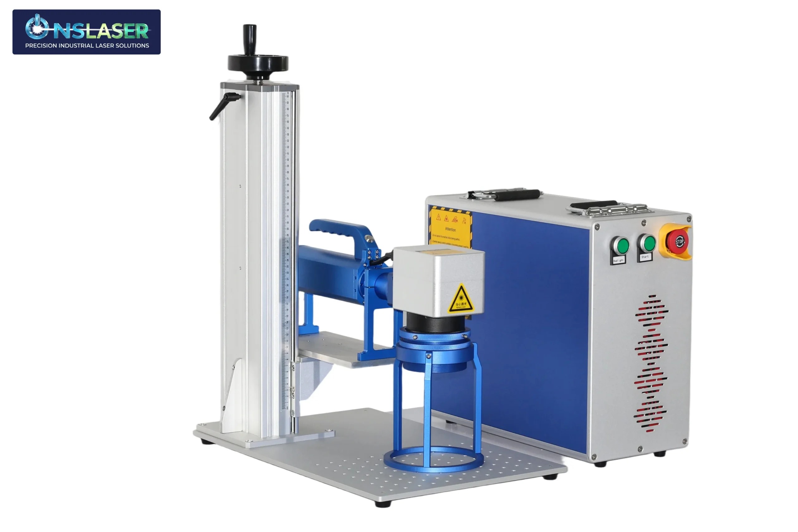
Selecting the right laser marking machine is a critical investment in your manufacturing quality and operational efficiency. At ONSlaser, we engineer advanced, industrial‑grade laser systems designed to seamlessly integrate into modern production lines—from high‑speed fiber solutions for metals to precision UV systems for sensitive polymers.
The video below is an operation video sent by one of our customers, who is very satisfied with the machine’s accurate positioning and ease of use.
Do you also want a laser marking machine that suits your needs? Contact Our Applications Team today to send your production samples for a free material compatibility test and receive a tailored equipment recommendation.