In global manufacturing and commercial supply chains, high-contrast, permanent product identification is a baseline requirement. Substandard marking equipment leads to blurry codes, damaged components, and catastrophic traceability failures that drive up warranty costs.
A viable fiber laser marking strategy requires a calculated evaluation of beam physics, kinematic motion tolerances, substrate absorption profiles, and emerging application trends. This guide breaks down the core technical variables to help procurement and engineering teams select the optimal system.
1. The Working Principle: How a Fiber Laser Works
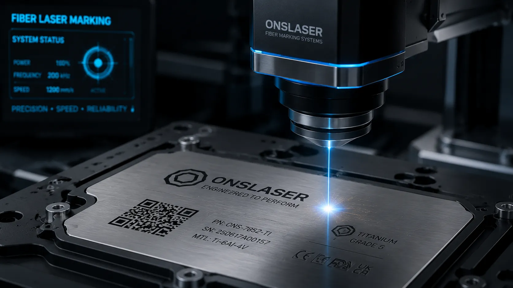
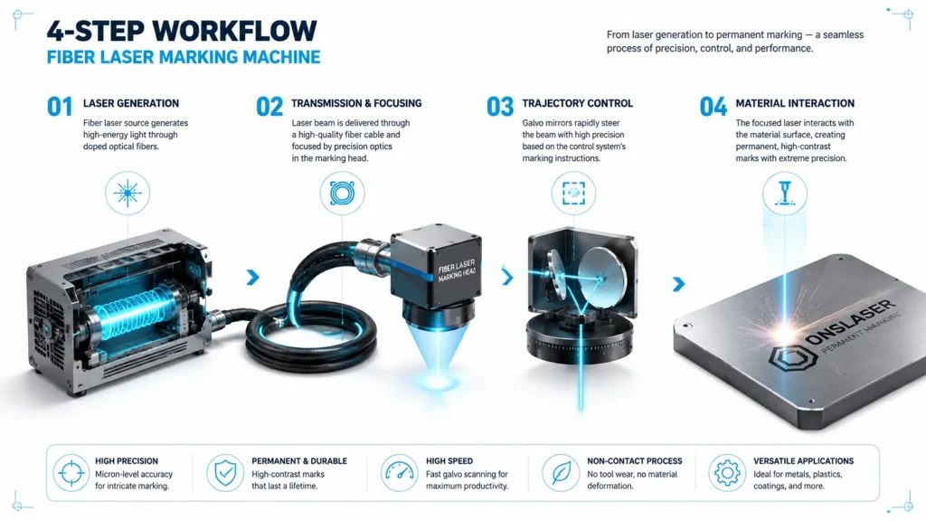
The operation of a fiber laser marking machine is best understood as using a highly precise “optical knife” to carve permanent traces into a material. The process operates in four straightforward, highly efficient stages:
Step 1: Laser Generation (The Power Engine)
The core component of the system is the fiber laser source. Once powered, internal pump sources emit light at a specific wavelength, exciting the rare-earth doped active gain medium within the optical fiber. Through a chain reaction of energy amplification, a high-energy laser beam is generated. This beam features a concentrated, fixed wavelength (typically 1064 nm), forming the exact foundation for high-speed, precise marking.
Step 2: Transmission and Focusing (Achieving Precise Control)
The generated laser beam travels to the marking head via a flexible fiber optic cable, which acts as a frictionless “light conduit,” eliminating power loss or beam deviation. This flexible delivery design allows for compact, portable machine configurations that integrate easily into tight production lines. Upon reaching the marking head, the beam passes through a lens assembly that compresses the raw light into a microscopic focal spot down to the micrometer (µm) level.
Step 3: Trajectory Control (Carving the Pattern)
Inside the marking head, a high-speed galvanometer (galvo) scanning system directs the focused laser spot across the material. Acting as a digital conductor, the galvo system moves internal mirrors to trace pre-configured text, logos, or 2D barcodes. Because the energy dose of every single coordinate point is completely controllable, the system renders intricate graphics and ultra-dense data matrices with total crispness.
Step 4: Material Interaction (The Final Identification)
When the high-energy beam contacts the substrate, it triggers a permanent physical or chemical change based on the material’s properties:
- For Metals (e.g., Stainless Steel, Aluminum): The localized energy instantly melts or vaporizes the surface, creating a micro-recessed mark that resists abrasion, corrosion, and fading.
- For Select Non-Metals (e.g., ABS Plastics, Ceramics): The laser induces a controlled oxidation or carbonation reaction, yielding a high-contrast color contrast without surface degradation.
💡 The Non-Contact Advantage vs. Legacy Marking
Compared to traditional methods like continuous inkjet (CIJ) printing or pneumatic dot peen marking, fiber lasers present distinct operational advantages:
- Inkjet Systems: Require ongoing fluid consumables, pose solvent-emission environmental risks, and produce marks susceptible to solvent wear or abrasion.
- Dot Peen Systems: Rely on mechanical contact that subjects the substrate to structural stress and lacks the resolution required for complex graphics.
- Fiber Lasers: Operate via a non-contact, consumable-free mechanism that draws only electrical power. This minimizes total cost of ownership (TCO), prevents structural deformation of fragile parts, and aligns with green manufacturing mandates.
2. Why Fiber Lasers Excel at Marking Metals
The dominance of fiber lasers in metal processing is a direct consequence of solid-state physics, specifically matching absorption spectra with thermal dynamics.
- Optimal NIR Absorption: At the 1064 nm near-infrared (NIR) wavelength, industrial metals—including carbon steel, stainless steel, aluminum, brass, and copper—exhibit high optical absorption coefficients. This ensures efficient energy coupling, minimizing back-reflection that could damage the laser source.
- Extreme Fluence (J/cm²): Metals feature high thermal conductivity and high melting points. Fiber lasers compress high average power into nanosecond bursts, yielding immense peak power densities that vaporize or melt material faster than the surrounding thermal conductivity can dissipate the heat.
- Minimized Heat-Affected Zone (HAZ): With an excellent beam quality factor (M² < 1.3), the optical energy is confined strictly to the programmed boundaries. This tight spatial control eliminates micro-cracking, heat warping, or metallurgical degradation in critical components.
3. Kinematic Control: Laser Precision & Galvanometer Motor Tolerances
In automated production environment, a system must deliver exceptional precision over millions of duty cycles. Mark legibility and barcode readability rely entirely on two control metrics:
3.1 The Value of Optical Precision
Laser precision dictates edge roughness and the absolute minimum readable feature size. High-end fiber systems maintain a Gaussian energy distribution across the focal spot, which provides:
- Crisp Boundary Definition: The sharp energy cutoff at the spot edge ensures clean material ablation without leaving slag, dross, or parasitic charring, creating visually premium branding marks.
- High-Density Data Packing: When engraving a dense 2×2 mm DataMatrix code containing dozens of characters, tight beam profiles prevent overlapping pixels, directly preserving high First Pass Yield (FPY) rates during machine vision inspections.
3.2 Analyzing and Mitigating Galvanometer Motor Drift
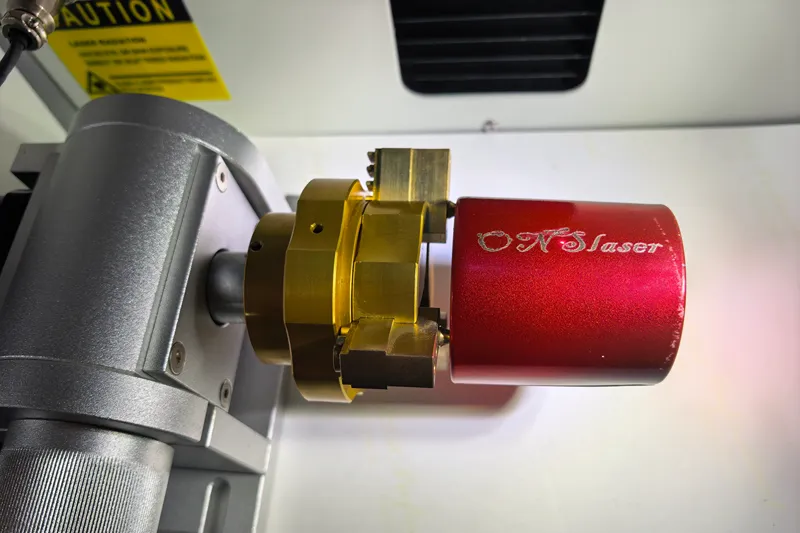
The dynamic steering of the beam is executed by closed-loop galvanometer motors. Microscopic deviations in motor tracking are the root cause of graphic distortion and positional errors.
- Thermal Drift: Continuous high-speed scanning generates internal heat within the galvo stator and feedback circuitry. A 1°C temperature shift can alter internal impedance, causing graphic skewing or line thickening over extended production runs. Industrial-grade platforms utilize temperature-compensated (digital) galvos to dynamically nullify this drift.
- Tracking and Hysteresis Error: When executing sharp 90-degree corners or complex vector paths at high speeds, rotor inertia can introduce microsecond delays, smoothing sharp corners into rounded edges. Mitigating this requires advanced digital controllers optimizing jump, open, and close delays, constraining dynamic repeatability tolerances to within ±1 µm.
4. Primary Commercial Application Sectors
Fiber laser systems have become the benchmark standard for high-volume tracking, brand elevation, and high-value luxury retail.
| Industrial & Commercial Sector | Primary Application Case | Technical Drivers & Key Metrics |
|---|---|---|
| Logo & Brand Identification | Premium consumer electronics, precision hand tools, anodized appliance faceplates. | High-resolution aesthetic contrast; enhances brand value and establishes a baseline barrier to counterfeit entry. |
| Serial Numbers & Direct Part Marking (DPM) | Automotive powertrain components, industrial asset tags, electronic sub-assemblies. | Guarantees permanent, life-of-part traceability capable of surviving abrasive friction, heat cycling, and post-process coating. |
| Precious Metals & Jewelry | Laser hallmarking (e.g., G750, 925), ring interior engraving, customized luxury micro-engraving. | Micro-focal spots allow legible marking on minimal surface areas with zero mass loss of high-value stock. |
| Hardware, Tooling & Dies | Toughened tool steels, bearing races, high-speed carbide cutting tools. | Deep engraving capabilities that remain readable even under prolonged mechanical wear and exposure to cutting oils. |
5. Current Technology Trends
Modern fiber systems are advancing beyond static, binary contrast marks by manipulating pulse structures and sub-micron surface chemistry.
5.1 Substrate Diversification: Extending to Polymers
While native 1064 nm light passes straight through clear polymers, modern fiber systems leverage advanced pulse control to mark opaque engineering plastics:
- Controlled Micro-Foaming: By utilizing MOPA (Master Oscillator Power Amplifier) architectures, operators can deploy ultra-short pulse widths at high frequencies. This keeps single-pulse energy low, triggering a controlled chemical color change or micro-foaming within plastics like ABS, PC, and Nylon without causing surface charring.
- Selective Coating Ablation: High peak powers allow the system to vaporize dark surface polymer coatings while leaving the underlying metal or composite substrate intact—a technique common in backlit electronic interfaces.
5.2 Transitioning to Structural Color Marking
Color laser marking represents the premium tier of modern surface texturing, utilizing MOPA technology to generate nanometer-scale structural color on stainless steel and titanium without external pigments.
Optical Path Difference (QPD) = 2 * n * d * cos(θ)
By delivering highly uniform thermal dosing, the laser controls the rapid growth of a transparent chromium oxide passive layer (thickness d, spanning tens to hundreds of nanometers).
When ambient light strikes the surface, reflections occur at both the upper boundary of the oxide film and the lower metal substrate interface. This produces Thin-Film Interference. Adjusting the pulse width and overlap ratio alters the oxide film’s thickness, allowing operators to reliably reproduce specific brilliant hues—such as golds, blues, and deep reds—solely through optical manipulation.
6. Procurement Framework: Selecting the Target System
Specifying an industrial fiber laser marking system requires aligning your hardware component selections with clear operational requirements:
- Select the Laser Engine (Q-Switched vs. MOPA): For general metal marking, high-volume serializing, deep tool engraving, and asset tagging, a standard Q-switched fiber laser offers excellent cost-to-performance efficiency. If your workflow involves sensitive polymers, ultra-precise jewelry engraving, or thin-film color marking, a MOPA architecture is mandatory due to its adjustable pulse width control.
- Evaluate Galvo Specifications: For high-speed, inline “marking-on-the-fly” conveyor setups, specify a digital galvo assembly equipped with onboard temperature compensation to prevent positional drift across multi-shift runs.
- Balance Average Power with Cycle Time: A 20W to 30W configuration is optimal for rapid surface marking, logo applications, and high-density barcodes. For deep mold engraving, fast surface cleaning, or heavy scaling ablation, transition to 50W or 100W+ power classes.
- Calculate True Total Cost of Ownership (TCO): Beyond the initial capital expenditure (CapEx), build a comprehensive cost model evaluating extraction filter replacement intervals, f-theta lens protection glass consumption, total electrical draw, and the vendor’s local field service level agreements (SLAs).
7. Conclusion
Optimizing a fiber laser marking installation is an exercise in balancing optical boundaries, mechanical accuracy, and capital efficiency. Before deploying any system to full-scale production, run validation trials using actual production-grade coupons. Locking in optimized pulse intervals, frequency matrices, and scan speed parameters within a centralized quality management system ensures your product marking remains clear, permanent, and compliant throughout the product lifecycle.
If you are interested in fiber lasers, please contact the ONSLASER technical team for more information.